Measuring range / features
0–10 / 20 / 25 / 25.4 / 50 mm/s RMS; 0–0.5 / 1.0 in/s by detector configuration. Peak is a separate option. Acceleration ranges 0–5 / 10 / 20 g by separate configuration.
 Vibration Transmitters
VTX-420 / LOOP POWERED
Two wires. One useful vibration trend.
Bring bearing-housing vibration into an existing PLC or DCS analog input. Request a two-wire transmitter with a defined RMS velocity range, frequency band and mounting interface.
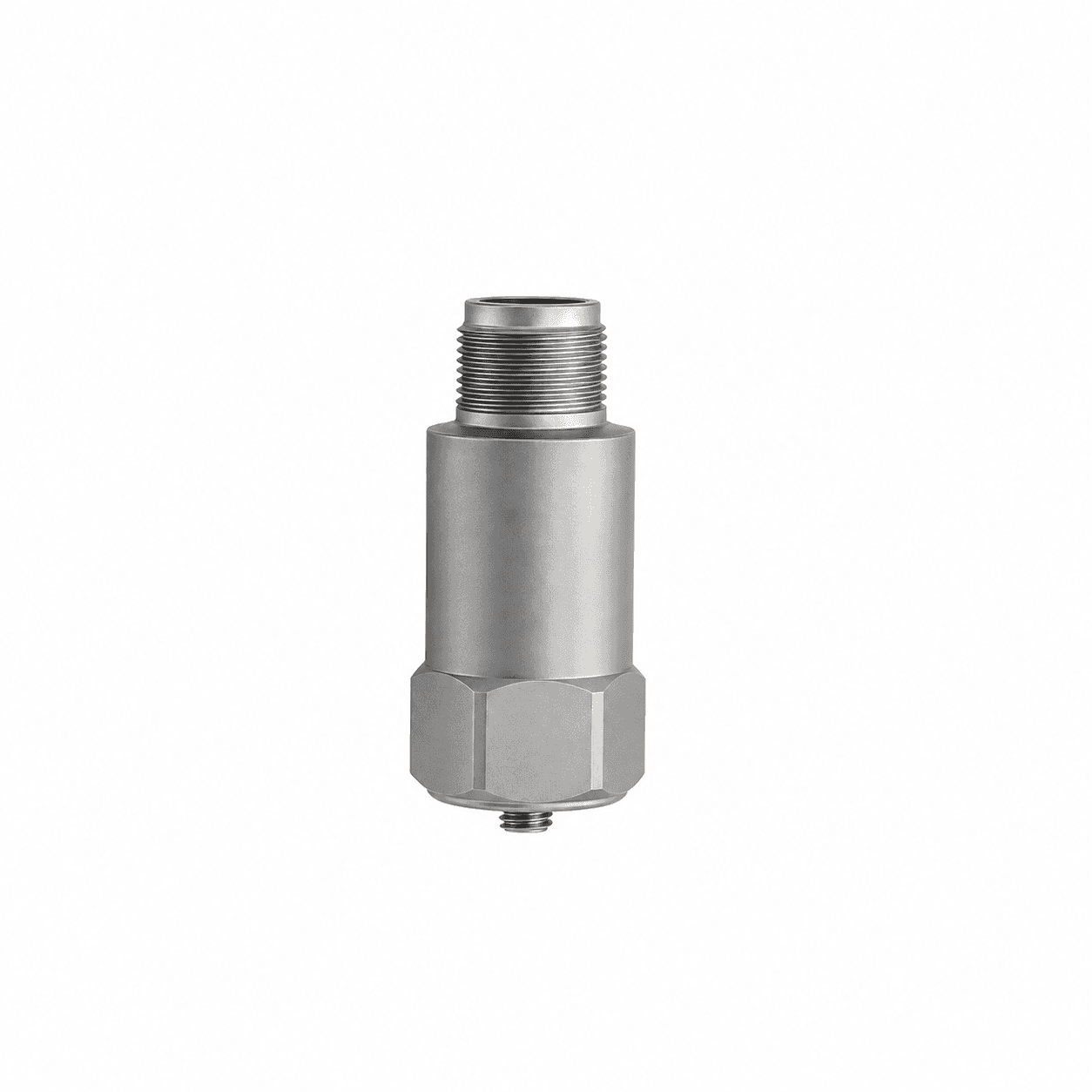
BEFORE YOU SPECIFY VTX-420
Confirm RMS or Peak, bandwidth, axis, minimum supply voltage at maximum current, isolation and full connector pinout. An overall RMS trend does not replace bearing fault spectrum analysis.
SIGNAL ARCHITECTURE / VTX-420
Plan the power and data path as one installation. The receiving input, cable or network and selected model determine the final connection.
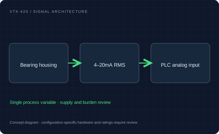
0–10 / 20 / 25 / 25.4 / 50 mm/s RMS; 0–0.5 / 1.0 in/s by detector configuration. Peak is a separate option. Acceleration ranges 0–5 / 10 / 20 g by separate configuration.
2-wire 4–20mA; supply and loop load qualified together. 12–30V DC is a configuration target, not a universal rating.
M8 × 1.25 / M6 / 1/4–28 UNF studs; M12, 2-pin MIL-C-5015 or integral cable; top / side exit by configuration.
Motors, centrifugal pumps, blowers, compressors, generators and bearing housings.
Configuration targets for quotation. Final ratings, released drawings, available reports and delivery are confirmed for the selected model.
MODEL / DETECTOR / BAND / INTERFACE
Select a model request profile and the interfaces to review. The written quotation establishes the final ordering code and released ratings.
2-wire 4–20mA velocity [RMS / Peak by configuration]
Confirm detector, full scale, supply/load and pinout.
Carry this configuration to RFQ →Request evaluation units →| Profile | Measurement | Band / timing | Interface | Confirm in quotation |
|---|---|---|---|---|
| VTX-420 Standard loop-powered velocity | Velocity RMS or Peak | 10–1000 Hz requested | M12 / MIL / integral cable | Confirm detector, full scale, supply/load and pinout. |
| VTX-420-LF Low-speed machine velocity | Low-frequency velocity | 2–1500 Hz requested | Top or side exit | Verify mounted low-frequency response and noise at actual RPM. |
| VTX-420T Velocity plus surface temperature | Velocity + temperature | Band and temperature span to confirm | Separate temperature conductors / loop | Specify PT100 or current output and the full wiring topology. |
| VTX-420D Velocity plus buffered dynamic output | 4–20mA + dynamic acceleration | Each output band to confirm | Separate dynamic acquisition connection | Confirm dynamic sensitivity, bias, power and analyzer loading. |
Copy the original detector convention into the request. Some originals report a sine-equivalent peak derived from RMS. Match that convention to the existing PLC scaling and alarm policy.
A 180 RPM shaft turns at 3 Hz. Request a low-frequency review rather than assuming a 10 Hz high-pass response covers the running-speed component. Confirm installed noise and response tolerance.
VTX-420T and VTX-420D requests use additional conductors and matched receiving inputs. Specify PT100 versus a temperature loop, or the analyzer sensitivity, loading and dynamic connector.
| Original document | Positive / current return | Review before connecting |
|---|---|---|
| IFM VTV122 | Pin 1 L+ / Pin 2 current output | Confirm the exact mating cordset and active/passive input. |
| Hansford HS-420 M12 TS029.8 | Pin 2 supply + / Pin 4 return | Confirm suffix and revision. A connector shell does not establish pin compatibility. |
| VTX request | Provide required pin numbers | The approved VTX drawing establishes polarity, shield and spare-pin treatment. |
Use minimum supply and the model’s maximum operating / fault current. Enter resistive drops and fixed drops once.
This budget covers voltage only. Intrinsic-safety entity parameters, isolation, tolerances, temperature and the full loop must be checked separately.
HOUSING / CONNECTION / INSTALLATION
Match the complete installation to the loop configuration. A similar housing does not establish detector, range or pinout compatibility.
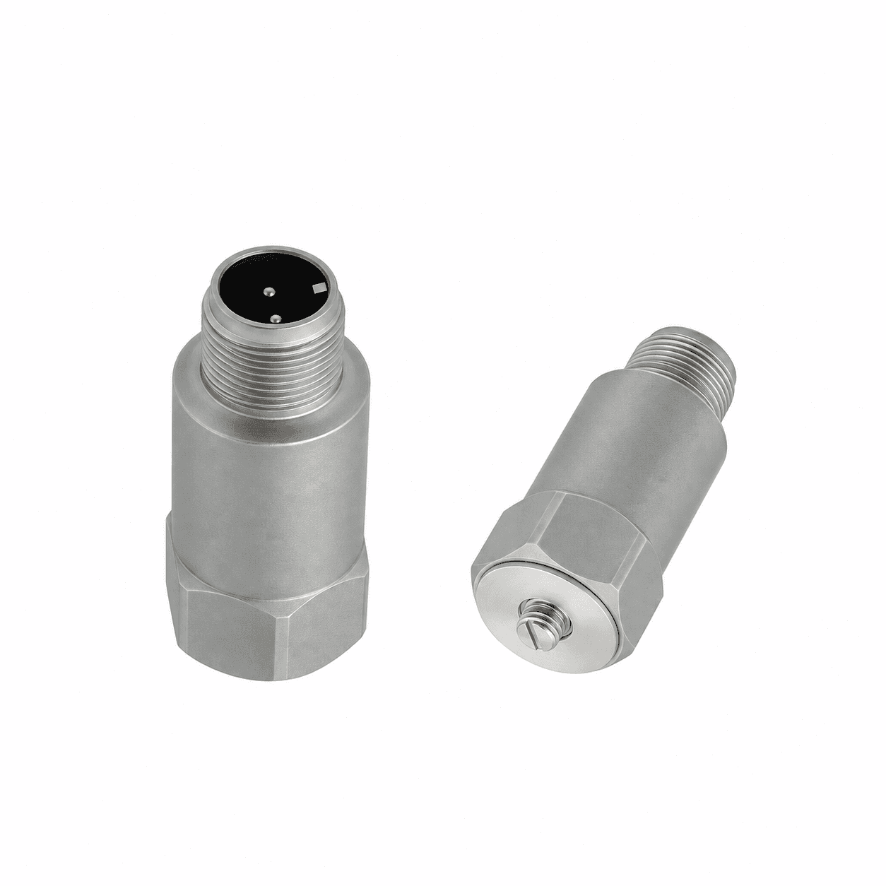
Check the mating connector, mounting thread and available tool clearance against the selected drawing.
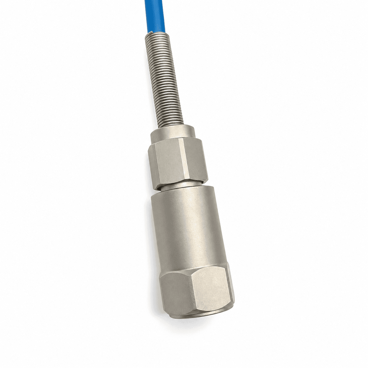
Specify cable length, jacket, bend radius and strain relief for the route from bearing housing to control cabinet.
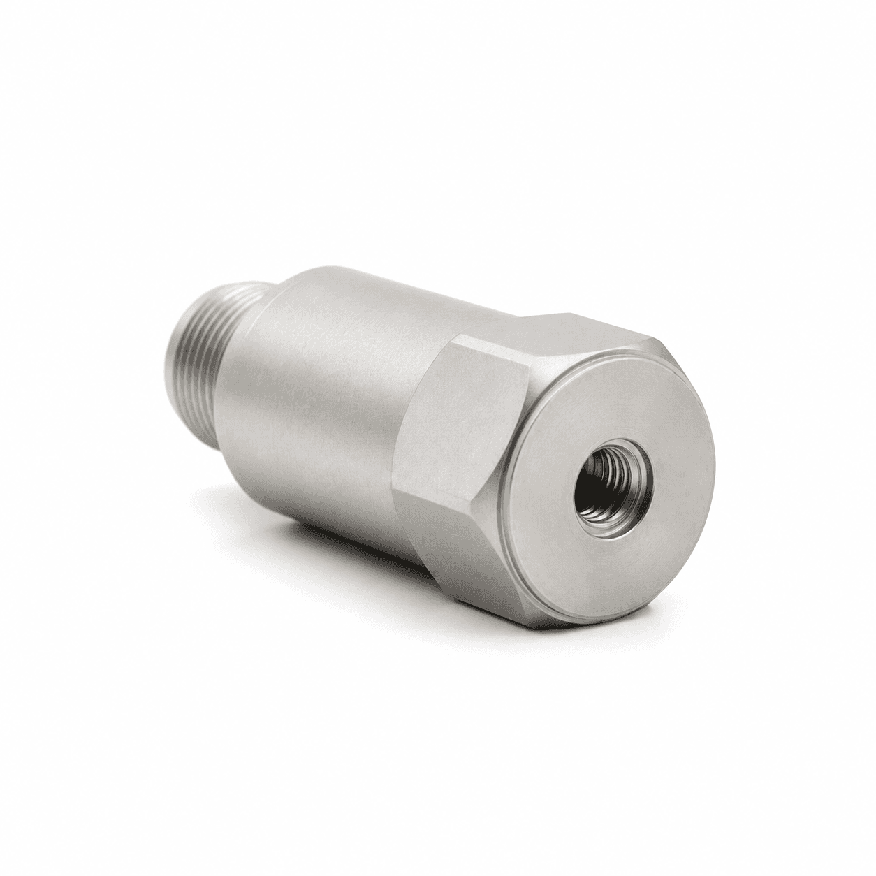
Confirm thread pitch, usable depth and the matching stud. Select acceleration or velocity as separate measurement configurations.
Available guides describe the request scope. The document center lists released drawings and model-specific evidence to obtain with your quotation.
RANGE / THREAD / CONNECTOR REVIEW
| Interface | Metric request | Imperial request | Check before ordering |
|---|---|---|---|
| Velocity units | 0–10 / 20 / 25 / 25.4 / 50 mm/s RMS | 0–0.5 / 1.0 / 2.0 in/s = 12.7 / 25.4 / 50.8 mm/s | Confirm RMS, Peak or derived Peak and the original full scale |
| Mounting stud | M8 × 1.25 or M6 | 1/4–28 UNF | Pitch, thread depth, gender, seating face and torque |
| Connection | M12 4-pin | 2-pin MIL-C-5015 | Exact pinout and mating connector; not implied by connector shape |
| Other interfaces | Integral cable / protected cable | 1/2 NPT conduit entry where applicable | A conduit thread is not interchangeable with a mounting stud |
Request options describe a configuration review, not a stock guarantee.
INSTALLATION KIT / FEWER LOOSE ENDS
A suitable pad, correctly wired cable and matched readout can simplify a plant rollout. Choose only the accessories your output needs in the form below.
Glue-on pads require a rigid, prepared mounting surface and qualified adhesive. Thin motor fins, fan guards and flexible covers are unsuitable default measurement points.
01 Prepared mounting pad & matched stud
02 PUR / armored cable or matched wireless gateway
03 Local display / relay monitor where applicable
04 Handheld meter for comparable spot-check readings
All kit options quoted separately. No preselected purchase obligation.Metrix ST5484E; IMI 640B01 / 641B; Wilcoxon PC420VR / PC420AR; Hansford HS-420; IFM VTV122. These are identification references only. Send the full suffix, datasheet and wiring drawing; there is no automatic drop-in or authorization claim.
List the required calibration method and traceability, enclosure rating, local conditions and certification scope. Only configuration-specific documents establish suitability; a housing style or series name is not evidence.
Share an asset list, measurement points per asset, control architecture, cable lengths and destination. Request a pilot configuration before a larger rollout. Pricing and lead time follow the reviewed bill of materials.
| Request code | Item | Quantity basis | Fit and environment review |
|---|---|---|---|
| VTX-ACC-PAD | Prepared glue-on pad / fin-mount adapter review | per mounting point | Rigid load path, actual fin geometry, adhesive, cure, temperature and installed response. |
| VTX-ACC-CBL | 5 m PUR / armored cable request | per cable assembly | Length, sheath, connector coding, pinout, cable restraint and temperature. |
| VTX-DIN | Local display and relay monitor | per monitored channel | Loop powering, engineering units, relay ratings and reset. |
| VTX-PEN | Portable vibration spot-check meter | per instrument | Detector, bandwidth, contact probe / mount and calibration scope. |
For a pilot, workshop or OEM rollout, request line-item unit prices at the exact quantity and destination. Include studs, cable lengths, calibration, freight and warranty terms in the quote.
Download quotation comparison CSV ↓PLANT-WIDE QUOTE / CAD REVIEW
Include the machine, original model and control input. Attach a nameplate or asset list and request the drawings and records needed for purchasing.
[email protected]Prefilled email carries your current selections. Add the listed files in your email client.
Ask for sensor-only and installation-kit line items at your exact quantity. Studs, calibration scope, warranty and delivery will appear in the written quote.
Download the asset-list CSVVibration Transmitters | Plant-wide vibration monitoring RFQ Name: Request profile: Configuration review Request purpose: Configuration advice / project review Band: Confirm band and response tolerance Exact quantity: To confirm Wireless kit: Not selected Documents requested: None Company / plant: Reply email: Series entry: VTX-420 Machine: Electric motors, pumps & fans Output: 2-wire 4–20mA velocity [RMS / Peak by configuration] Range: Confirm range / digital features in brief Connector / mounting: Other / confirm with drawing Mounting thread: Confirm thread, gender and depth in brief Connection exit: Confirm from model / clearance drawing Original pinout to review: To confirm from drawing Detector: Confirm per configuration Original model: Not specified Quantity band: 1-5 Accessories: None Source: /4-20ma-velocity-vibration-transmitters/ Operating speed / RPM: To confirm Ambient / bearing temperature: To confirm PLC / receiving system: To confirm Destination country / site: To confirm Interface and operating requirements: To confirm during configuration review Project brief: Configuration, certification, compatibility, price and delivery subject to written review.
OTHER SIGNAL PATHS