Measuring range / features
Requested displacement 0–10 / 20 mm peak-to-peak, or heavy-duty low-frequency velocity. Confirm operating frequency and maximum shock independently.
 Vibration Transmitters
VTX-SCR / HARSH DUTY REVIEW
Measure the process motion before judging the machine.
Specify vibration measurement sensors for screens, crushers and mills, or review vibration monitoring for oil and gas machines. Measurement range, low-frequency response and installation conditions come first.
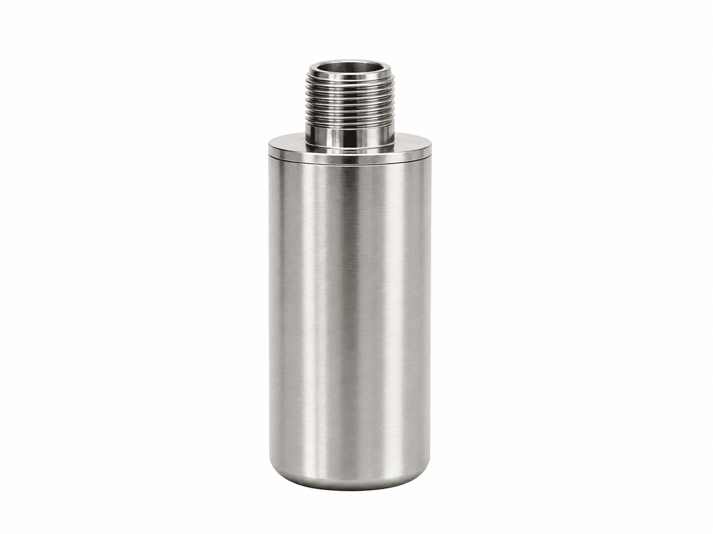
BEFORE YOU SPECIFY VTX-SCR
An Ex-style housing does not establish ATEX / IECEx approval. Supply zone, gas or dust group, temperature class and certificate requirements before any hazardous-area recommendation.
SIGNAL ARCHITECTURE / VTX-SCR
Plan the power and data path as one installation. The receiving input, cable or network and selected model determine the final connection.
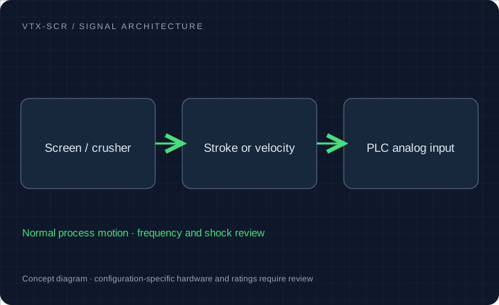
Requested displacement 0–10 / 20 mm peak-to-peak, or heavy-duty low-frequency velocity. Confirm operating frequency and maximum shock independently.
4–20mA output with overload / saturation behavior to confirm; armored cable routing and plant grounding review.
Rigid, prepared machine pad and protected armored cable. Mount position, machine movement and cable fatigue need a site drawing.
Mining vibrating screens, crushers and mills; separate certification-led review for oil and gas rotating machinery.
Configuration targets for quotation. Final ratings, released drawings, available reports and delivery are confirmed for the selected model.
MODEL / DETECTOR / BAND / INTERFACE
Select a model request profile and the interfaces to review. The written quotation establishes the final ordering code and released ratings.
4–20mA displacement [mm peak-to-peak]
Specify stroke, frequency, shock and cable restraint drawing.
Carry this configuration to RFQ →Request evaluation units →| Profile | Measurement | Band / timing | Interface | Confirm in quotation |
|---|---|---|---|---|
| VTX-SCR Screen stroke / heavy-duty motion | 0–10 / 20 mm peak-to-peak requested | Operating frequency and shock to confirm | 4–20mA + protected cable | Specify stroke, frequency, shock and cable restraint drawing. |
| VTX-420-EX Hazardous-area configuration review | Velocity / acceleration by configuration | Machine-specific band to confirm | 1/2 NPT / M20 conduit request | Certification availability, full marking and loop parameters require review. |
Use this sine-motion example to check whether a normal motor transmitter range fits intentional screen motion.
900 RPM and 10 mm stroke give about 333.2 mm/s RMS under sinusoidal motion. Actual waveform, overload survival, passband and output saturation require the selected sensor documentation.
Provide normal and maximum peak-to-peak stroke, machine speed, axis and impact duty. Quote the displacement band, overload limit and saturation behavior together.
Show the sensor location, restrained lead, moving loop, bend radius and transition to stationary cable. Include guarding against flying material and the maintenance removal path.
Specify gas/dust area, temperature class, ambient range, certificate requirements and 1/2 NPT or M20×1.5 conduit request. For intrinsic safety, include the barrier entity parameters and cable capacitance/inductance.
Review the compliance document list →HOUSING / CONNECTION / INSTALLATION
Low-frequency housing examples help plan the installation. Required displacement span, shock survival and overload behavior need separate configuration evidence.
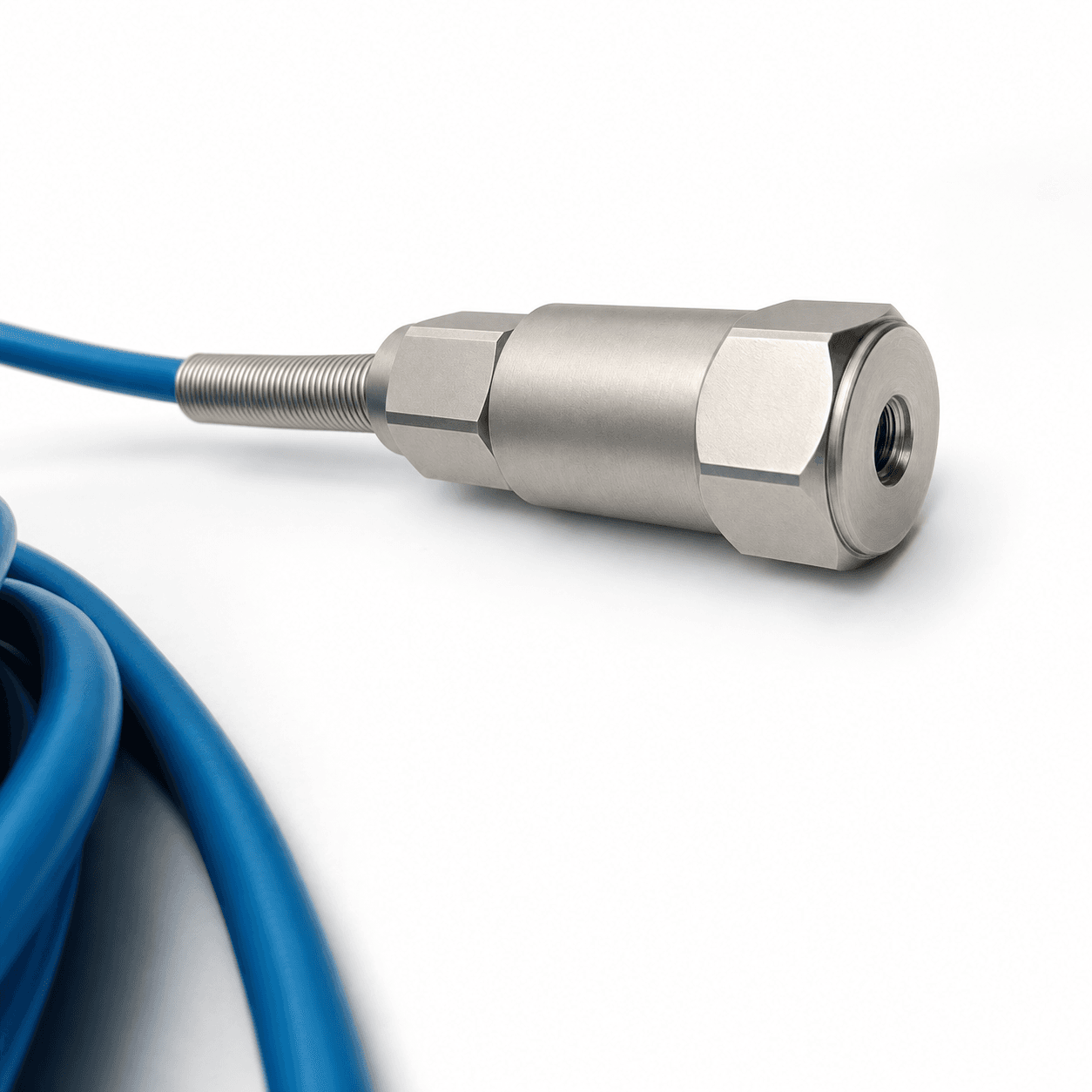
Review movement, impact exposure and routing. Request the required cable protection rather than infer it from a housing photo.
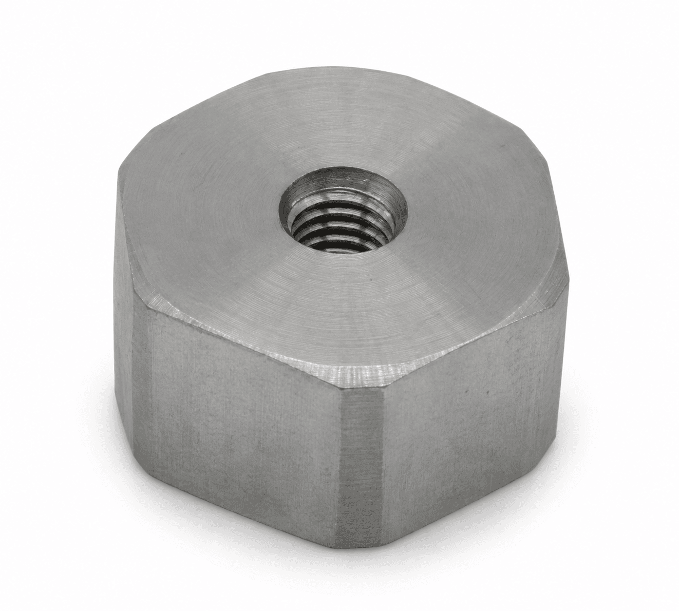
Check surface preparation, stiffness, adhesive qualification or a machined mounting face for the measurement point.
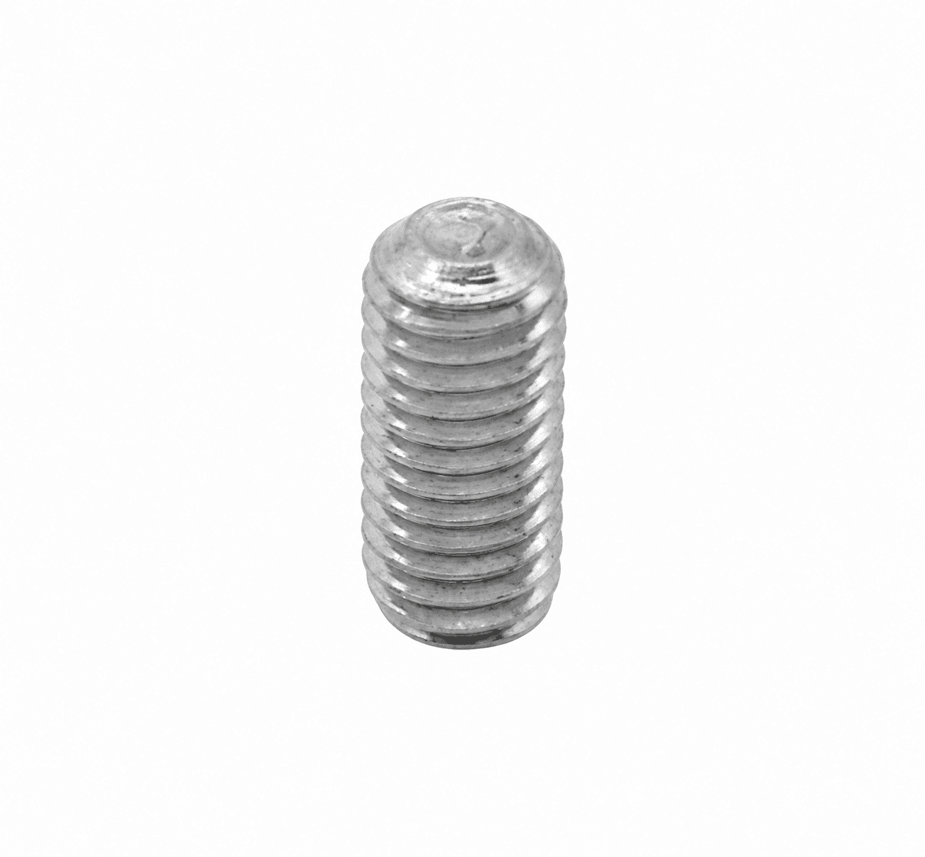
Specify both mating threads, engagement depth and installation torque in the controlled drawing.
Available guides describe the request scope. The document center lists released drawings and model-specific evidence to obtain with your quotation.
RANGE / THREAD / CONNECTOR REVIEW
| Interface | Metric request | Imperial request | Check before ordering |
|---|---|---|---|
| Velocity units | 0–10 / 20 / 25 / 25.4 / 50 mm/s RMS | 0–0.5 / 1.0 / 2.0 in/s = 12.7 / 25.4 / 50.8 mm/s | Confirm RMS, Peak or derived Peak and the original full scale |
| Mounting stud | M8 × 1.25 or M6 | 1/4–28 UNF | Pitch, thread depth, gender, seating face and torque |
| Connection | M12 4-pin | 2-pin MIL-C-5015 | Exact pinout and mating connector; not implied by connector shape |
| Other interfaces | Integral cable / protected cable | 1/2 NPT conduit entry where applicable | A conduit thread is not interchangeable with a mounting stud |
For screen displacement, specify mm peak-to-peak and operating frequency; velocity units do not define stroke.
INSTALLATION KIT / FEWER LOOSE ENDS
A suitable pad, correctly wired cable and matched readout can simplify a plant rollout. Choose only the accessories your output needs in the form below.
Glue-on pads require a rigid, prepared mounting surface and qualified adhesive. Thin motor fins, fan guards and flexible covers are unsuitable default measurement points.
01 Prepared mounting pad & matched stud
02 PUR / armored cable or matched wireless gateway
03 Local display / relay monitor where applicable
04 Handheld meter for comparable spot-check readings
All kit options quoted separately. No preselected purchase obligation.IMI 645B and Hansford references require full-range and passband review. An original mil-scale displacement transmitter is not an automatic match for a 10–20 mm screen stroke. These are identification references only. Send the full suffix, datasheet and wiring drawing; there is no automatic drop-in or authorization claim.
List the required calibration method and traceability, enclosure rating, local conditions and certification scope. Only configuration-specific documents establish suitability; a housing style or series name is not evidence.
Share an asset list, measurement points per asset, control architecture, cable lengths and destination. Request a pilot configuration before a larger rollout. Pricing and lead time follow the reviewed bill of materials.
| Request code | Item | Quantity basis | Fit and environment review |
|---|---|---|---|
| VTX-ACC-PAD | Prepared glue-on pad / fin-mount adapter review | per mounting point | Rigid load path, actual fin geometry, adhesive, cure, temperature and installed response. |
| VTX-ACC-CBL | 5 m PUR / armored cable request | per cable assembly | Length, sheath, connector coding, pinout, cable restraint and temperature. |
| VTX-DIN | Local display and relay monitor | per monitored channel | Loop powering, engineering units, relay ratings and reset. |
| VTX-PEN | Portable vibration spot-check meter | per instrument | Detector, bandwidth, contact probe / mount and calibration scope. |
For a pilot, workshop or OEM rollout, request line-item unit prices at the exact quantity and destination. Include studs, cable lengths, calibration, freight and warranty terms in the quote.
Download quotation comparison CSV ↓PLANT-WIDE QUOTE / CAD REVIEW
Include the machine, original model and control input. Attach a nameplate or asset list and request the drawings and records needed for purchasing.
[email protected]Prefilled email carries your current selections. Add the listed files in your email client.
Ask for sensor-only and installation-kit line items at your exact quantity. Studs, calibration scope, warranty and delivery will appear in the written quote.
Download the asset-list CSVVibration Transmitters | Plant-wide vibration monitoring RFQ Name: Request profile: Configuration review Request purpose: Configuration advice / project review Band: Confirm band and response tolerance Exact quantity: To confirm Wireless kit: Not selected Documents requested: None Company / plant: Reply email: Series entry: VTX-SCR Machine: Mining vibrating screens & crushers Output: 4–20mA displacement [mm peak-to-peak] Range: Displacement range — specify mm peak-to-peak Connector / mounting: Other / confirm with drawing Mounting thread: Confirm thread, gender and depth in brief Connection exit: Confirm from model / clearance drawing Original pinout to review: To confirm from drawing Detector: Peak-to-peak displacement Original model: Not specified Quantity band: 1-5 Accessories: None Source: /mining-screen-oil-gas-vibration-sensors/ Operating speed / RPM: To confirm Ambient / bearing temperature: To confirm PLC / receiving system: To confirm Destination country / site: To confirm Interface and operating requirements: To confirm during configuration review Project brief: Configuration, certification, compatibility, price and delivery subject to written review.
OTHER SIGNAL PATHS