Identity and reference conditions
Check model, unique serial, date, detector, full scale, test temperature, mounting and reference instrument. Ask how the reference calibration is traced and whether the claimed scope covers the work.
 Vibration Transmitters
CALIBRATION / SERIAL NUMBER / MEASUREMENT CHAIN
Define the evidence your receiving inspection needs before the hardware is ordered. Match each instrument’s detector, range and current output to its model and serial-number record. Record the PLC input checks and agreed criteria for your evaluation units.
Request calibration scope & specimen →Record a 4–20mA pilot loop check ↓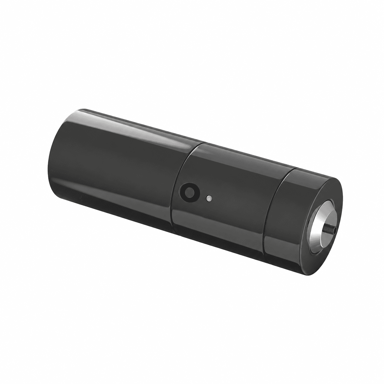
PILOT EVALUATION / PLC INPUT SCALING
Enter observations collected under your plant’s approved commissioning procedure. The initial 0–25.4 mm/s span and 4 / 12 / 20mA points are worksheet examples. Set the actual channel scale and record its displayed readings. Enter the endpoints and readings in the selected engineering unit.
| Applied current (mA) | PLC indication (mm/s) | Expected (mm/s) | Signed error (mm/s) | Error (% span) | Observation |
|---|---|---|---|---|---|
| 0.000 | — | — | Pending reading | ||
| 12.700 | — | — | Pending reading | ||
| 25.400 | — | — | Pending reading |
Expected = low + (mA − 4) ÷ 16 × (high − low). Percentage error uses the configured engineering span. Currents outside 4–20mA are retained for module-specific diagnostic review. Agree acceptance limits with the responsible plant engineer.
Vibration Transmitters | 4–20mA PLC loop scaling record
Exported UTC | Captured at copy / download
Loop / asset tag |
Entered instrument model / serial |
PLC / analog input channel |
Engineering unit | mm/s
Recorded detector | Confirm per configuration
Engineering value at 4mA | 0
Engineering value at 20mA | 25.4
Agreed criteria / follow-up |
Test conditions / reference instrument |
Scope | Entered current and PLC indication compared with the configured linear span. Acceptance criteria and review outcome are supplied by the responsible plant engineer.

Applied current (mA) | PLC indication | Expected indication | Indication error | Error (% span) | Observation status
4 |  | 0 |  |  | Pending reading
12 |  | 12.7 |  |  | Pending reading
20 |  | 25.4 |  |  | Pending reading
Download the CSV before leaving this page. Attach it to your RFQ and paste the copied brief into the project notes.
| Check | Conditions to record | Evidence for review |
|---|---|---|
| PLC input scaling | Configured current mode, engineering endpoints, input filter and reference current source. | Applied current, displayed PLC value, calculated indication error and buyer-approved criteria. |
| Transmitter measurement chain | Model, serial number, quantity, detector, range, reference vibration, method and uncertainty. | Configuration-specific calibration report and reference traceability. |
| Installed machine pilot | Mounting, measurement direction, speed, operating load, band, temperature and baseline. | Approved commissioning observations, trend review and corrective actions before rollout. |
The worksheet applies linear normalization to the entered 4–20mA span, then maps it to the configured engineering endpoints. Siemens documents these normalization and scaling operations. The PLC’s actual raw-count endpoints depend on the selected channel configuration. Siemens NORM_X / SCALE_X documentation ↗
Record the receiving module, signal and engineering endpoints, sample period and filter settings used for the test. Rockwell’s module configuration documentation identifies these settings. Use the manual for your actual module when checking overrange and diagnostic behavior. Rockwell analog-input configuration documentation ↗
Review module scaling and loop-load calculations →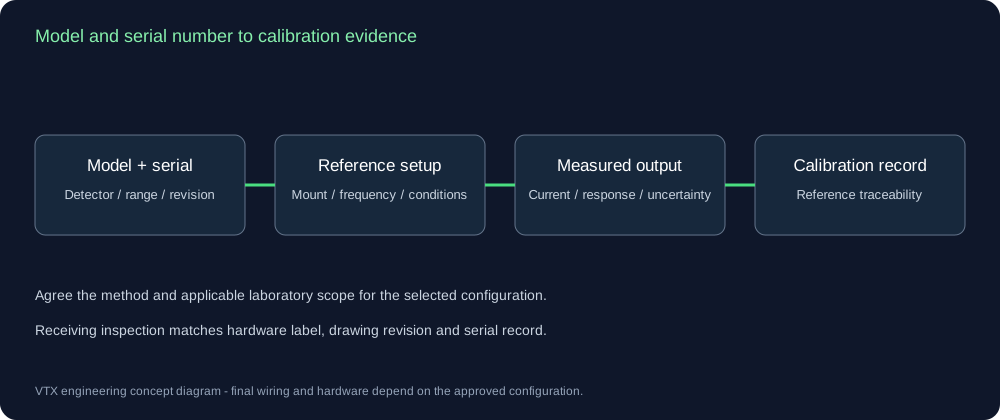
A useful calibration record identifies the measurement quantity, detector and output scale. Comparison calibration methods such as ISO 16063-21 require a defined reference and procedure. Agree the actual method, laboratory scope and uncertainty with the supplier for your configuration.
Check model, unique serial, date, detector, full scale, test temperature, mounting and reference instrument. Ask how the reference calibration is traced and whether the claimed scope covers the work.
Request zero/current offset, sensitivity at a stated reference frequency, measured current at specified vibration levels and relevant frequency response points. Include limits and uncertainty in the acceptance agreement.
Match the received label to the quoted drawing, report serial number and wiring. Check zero, span and machine mounting against your approved installation and commissioning procedure.
ISO 16063-21 official scope and amendments ↗
| Installation concern | Evidence to request |
|---|---|
| Material and sealing | Specified housing material, weld/seal process, enclosure test conditions, connector/cable assembly and report applicability. |
| VFD interference | EMC test scope and configuration, circuit-to-case isolation, cable/shield connection and installation instructions. |
| Temperature and cleaning | Operating/storage limits, thermal test scope, cleaning media and assembled connector/cable rating. |
| Warranty / replacement | Written duration, coverage, returns, installation obligations and lead-time arrangements for the quoted order. |
| Required record | Details to check | Current availability |
|---|---|---|
| Released datasheet | Selected model, detector, range, frequency response, power/load, environment and pinout. | Request for the selected configuration with your quotation. |
| Controlled drawing / STEP | Revision, thread gender/pitch/depth, envelope, cable exit and mating clearance. | Request for the selected configuration with your quotation. |
| Calibration specimen | Model, serial number, method, conditions, current scaling, detector, uncertainty and reference traceability. | Request for the selected configuration with your quotation. |
| CE / EMC / RoHS / ingress | Applicable configuration, test scope, responsible issuer and document revision. | Request for the selected configuration with your quotation. |
| ATEX / IECEx | Exact model/marking, holder, certificate status, special conditions and required system parameters. | Request for the selected configuration with your quotation. |
PLANT-WIDE QUOTE / CAD REVIEW
Include the machine, original model and control input. Attach a nameplate or asset list and request the drawings and records needed for purchasing.
[email protected]Prefilled email carries your current selections. Add the listed files in your email client.
Ask for sensor-only and installation-kit line items at your exact quantity. Studs, calibration scope, warranty and delivery will appear in the written quote.
Download the asset-list CSVVibration Transmitters | Plant-wide vibration monitoring RFQ Name: Request profile: Configuration review Request purpose: Configuration advice / project review Band: Confirm band and response tolerance Exact quantity: To confirm Wireless kit: Not selected Documents requested: None Company / plant: Reply email: Series entry: Unspecified Machine: Electric motors, pumps & fans Output: 2-wire 4–20mA velocity [RMS / Peak by configuration] Range: Confirm range / digital features in brief Connector / mounting: Other / confirm with drawing Mounting thread: Confirm thread, gender and depth in brief Connection exit: Confirm from model / clearance drawing Original pinout to review: To confirm from drawing Detector: Confirm per configuration Original model: Not specified Quantity band: 1-5 Accessories: None Source: /calibration-quality-assurance/ Operating speed / RPM: To confirm Ambient / bearing temperature: To confirm PLC / receiving system: To confirm Destination country / site: To confirm Interface and operating requirements: To confirm during configuration review Project brief: Configuration, certification, compatibility, price and delivery subject to written review.