Measuring range / features
RMS velocity setpoint and range by configuration; requested 2–15 s delay is qualified against machine run-up and protection requirements.
 Vibration Transmitters
VTX-SW / ALARM + RELAY
Make alarm behavior part of the specification.
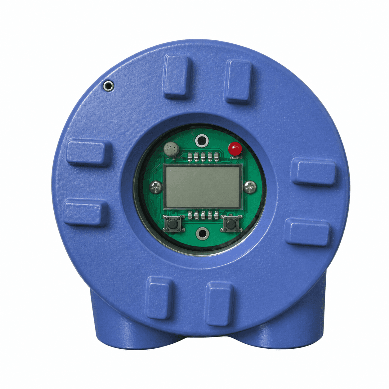
Request an electronic vibration switch or local DIN-rail monitor for machines needing a visible reading and a defined alarm interface. Specify startup delay, reset behavior and the complete relay circuit.
BEFORE YOU SPECIFY VTX-SW
No SIL or safety-function claim is made. A delay that suppresses startup motion can also postpone a needed trip; protective logic requires a machine-level review.
SIGNAL ARCHITECTURE / VTX-SW
Plan the power and data path as one installation. The receiving input, cable or network and selected model determine the final connection.
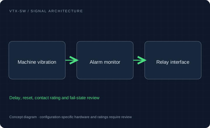
RMS velocity setpoint and range by configuration; requested 2–15 s delay is qualified against machine run-up and protection requirements.
SPDT / DPDT relay options and optional 4–20mA retransmission. Contact voltage, current, inductive duty and power-loss state require confirmation.
Machine-mounted switch or separate DIN-rail / panel monitor. Conduit entries, studs and signal wiring are separate mechanical requirements.
Cooling-tower fans, unattended compressors, blower packages and local machine alarm circuits.
Configuration targets for quotation. Final ratings, released drawings, available reports and delivery are confirmed for the selected model.
MODEL / DETECTOR / BAND / INTERFACE
Select a model request profile and the interfaces to review. The written quotation establishes the final ordering code and released ratings.
Electronic relay trip switch
Confirm external supply, startup delay, reset and power-loss state.
Carry this configuration to RFQ →Request evaluation units →| Profile | Measurement | Band / timing | Interface | Confirm in quotation |
|---|---|---|---|---|
| VTX-SW Electronic vibration relay monitor | Alarm / trip setpoint review | Filter and delay to confirm | Relay + optional current output | Confirm external supply, startup delay, reset and power-loss state. |
| VTX-DIN DIN-rail display + alarm monitor | 4–20mA process input / local display | Input update / alarm delay to confirm | 35 mm rail / panel format by option | Confirm whether the input powers the loop, relay rating and reset logic. |
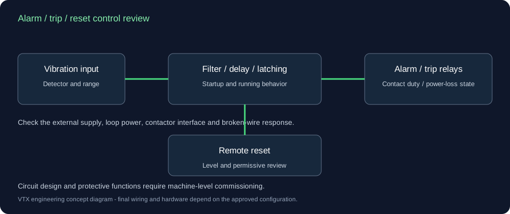
Request the supply, detector, alarm and trip setpoints, contact ratings and startup/operating delays separately. Agree the available adjustment range with the selected configuration.
Specify the 4–20mA input, whether loop power is needed, display units, 35mm rail or panel format, relay count and reset input. Include the sensor and input load in the loop budget.
Provide the bolt pattern and contactor circuit. Passive mechanical switches may have no supply conductors at the mounting point. Review an external supply, adapter plate, reset behavior and loss-of-power response.
| Condition | Required control decision |
|---|---|
| Run-up | Startup bypass or delay, maximum allowed protection delay. |
| Normal operation | Relay energized state and configured hysteresis. |
| High vibration | Alarm/trip action, operating delay and latching. |
| Broken wire / power loss | Fault indication and selected de-energized contact behavior. |
| Remote reset | Input level, reset permissive and manual restart policy. |
HOUSING / CONNECTION / INSTALLATION
Agree which device measures vibration and which receives a process signal. Relay, reset and startup-delay behavior follow the selected circuit.
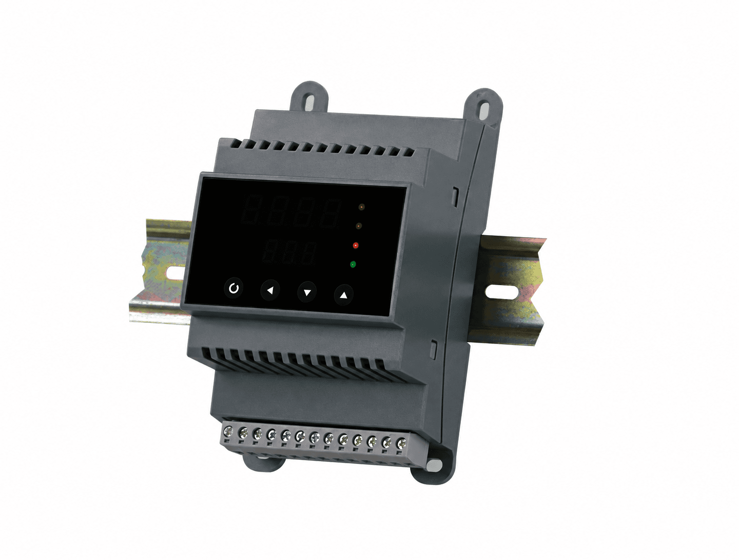
A cabinet module can receive a compatible process signal. Confirm relay ratings, power and input scaling; it is not a raw-waveform vibration analyzer.
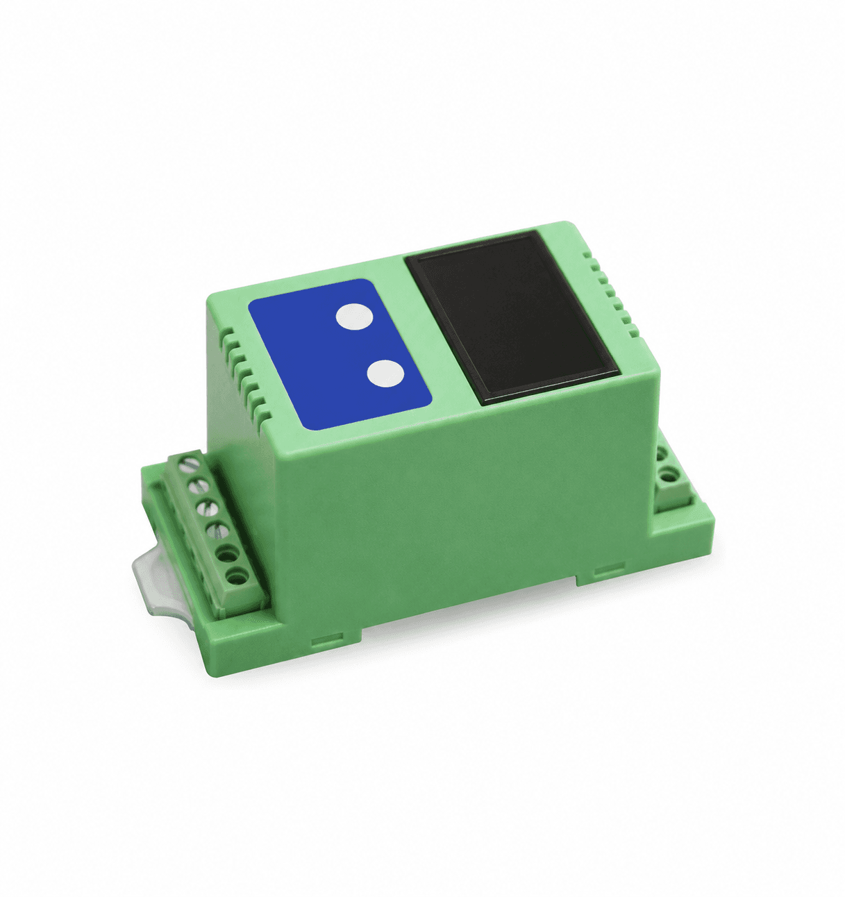
Review the selected display supply, loop burden, engineering units and available alarm outputs.
Available guides describe the request scope. The document center lists released drawings and model-specific evidence to obtain with your quotation.
RANGE / THREAD / CONNECTOR REVIEW
| Interface | Metric request | Imperial request | Check before ordering |
|---|---|---|---|
| Velocity units | 0–10 / 20 / 25 / 25.4 / 50 mm/s RMS | 0–0.5 / 1.0 / 2.0 in/s = 12.7 / 25.4 / 50.8 mm/s | Confirm RMS, Peak or derived Peak and the original full scale |
| Mounting stud | M8 × 1.25 or M6 | 1/4–28 UNF | Pitch, thread depth, gender, seating face and torque |
| Connection | M12 4-pin | 2-pin MIL-C-5015 | Exact pinout and mating connector; not implied by connector shape |
| Other interfaces | Integral cable / protected cable | 1/2 NPT conduit entry where applicable | A conduit thread is not interchangeable with a mounting stud |
Request options describe a configuration review, not a stock guarantee.
INSTALLATION KIT / FEWER LOOSE ENDS
A suitable pad, correctly wired cable and matched readout can simplify a plant rollout. Choose only the accessories your output needs in the form below.
Glue-on pads require a rigid, prepared mounting surface and qualified adhesive. Thin motor fins, fan guards and flexible covers are unsuitable default measurement points.
01 Prepared mounting pad & matched stud
02 PUR / armored cable or matched wireless gateway
03 Local display / relay monitor where applicable
04 Handheld meter for comparable spot-check readings
All kit options quoted separately. No preselected purchase obligation.Metrix SW5484E; Murphy VS2; IMI 685B. A passive mechanical switch and a powered electronic monitor are not automatically interchangeable. Confirm an external supply is available, plus reset and loss-of-power behavior. These are identification references only. Send the full suffix, datasheet and wiring drawing; there is no automatic drop-in or authorization claim.
List the required calibration method and traceability, enclosure rating, local conditions and certification scope. Only configuration-specific documents establish suitability; a housing style or series name is not evidence.
Share an asset list, measurement points per asset, control architecture, cable lengths and destination. Request a pilot configuration before a larger rollout. Pricing and lead time follow the reviewed bill of materials.
| Request code | Item | Quantity basis | Fit and environment review |
|---|---|---|---|
| VTX-ACC-PAD | Prepared glue-on pad / fin-mount adapter review | per mounting point | Rigid load path, actual fin geometry, adhesive, cure, temperature and installed response. |
| VTX-ACC-CBL | 5 m PUR / armored cable request | per cable assembly | Length, sheath, connector coding, pinout, cable restraint and temperature. |
| VTX-DIN | Local display and relay monitor | per monitored channel | Loop powering, engineering units, relay ratings and reset. |
| VTX-PEN | Portable vibration spot-check meter | per instrument | Detector, bandwidth, contact probe / mount and calibration scope. |
For a pilot, workshop or OEM rollout, request line-item unit prices at the exact quantity and destination. Include studs, cable lengths, calibration, freight and warranty terms in the quote.
Download quotation comparison CSV ↓PLANT-WIDE QUOTE / CAD REVIEW
Include the machine, original model and control input. Attach a nameplate or asset list and request the drawings and records needed for purchasing.
[email protected]Prefilled email carries your current selections. Add the listed files in your email client.
Ask for sensor-only and installation-kit line items at your exact quantity. Studs, calibration scope, warranty and delivery will appear in the written quote.
Download the asset-list CSVVibration Transmitters | Plant-wide vibration monitoring RFQ Name: Request profile: Configuration review Request purpose: Configuration advice / project review Band: Confirm band and response tolerance Exact quantity: To confirm Wireless kit: Not selected Documents requested: None Company / plant: Reply email: Series entry: VTX-SW Machine: Cooling towers Output: Electronic relay trip switch Range: Confirm range / digital features in brief Connector / mounting: Other / confirm with drawing Mounting thread: Confirm thread, gender and depth in brief Connection exit: Confirm from model / clearance drawing Original pinout to review: To confirm from drawing Detector: Confirm per configuration Original model: Not specified Quantity band: 1-5 Accessories: None Source: /electronic-vibration-switches-monitors/ Operating speed / RPM: To confirm Ambient / bearing temperature: To confirm PLC / receiving system: To confirm Destination country / site: To confirm Interface and operating requirements: To confirm during configuration review Project brief: Configuration, certification, compatibility, price and delivery subject to written review.
OTHER SIGNAL PATHS