Measuring range / features
X/Y/Z RMS velocity, acceleration, displacement peak-to-peak and °C; available channels, filters and FFT features confirmed per configuration.
 Vibration Transmitters
VTX-MOD / SMART MONITORING
Vibration and temperature, in the same data path.
Specify industrial vibration monitoring sensors for triaxial velocity, acceleration, displacement features and bearing surface temperature. Choose the interface that fits your control architecture.
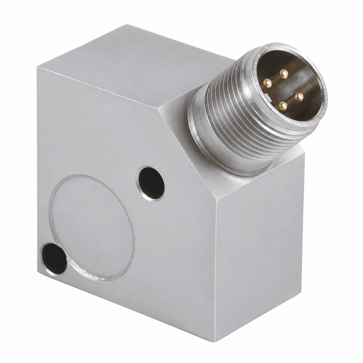
BEFORE YOU SPECIFY VTX-MOD
Confirm register map / IODD, feature units, update rates, axis orientation and temperature location. RS485 node count depends on transceiver loading, cable, termination and baud rate.
SIGNAL ARCHITECTURE / VTX-MOD
Plan the power and data path as one installation. The receiving input, cable or network and selected model determine the final connection.
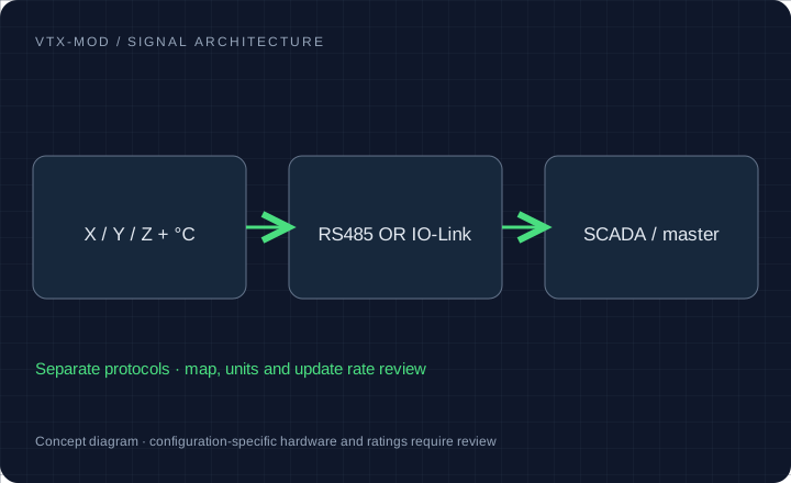
X/Y/Z RMS velocity, acceleration, displacement peak-to-peak and °C; available channels, filters and FFT features confirmed per configuration.
RS485 Modbus RTU or IO-Link as separate interface options. Requested supply envelope 9–36V DC, subject to selected model.
Rigid bearing-housing mount; M8 or 1/4–28 by option. Connector, axis orientation and housing clearance reviewed together.
SCADA-connected production lines, OEM machines, pump skids and distributed motor condition monitoring.
Configuration targets for quotation. Final ratings, released drawings, available reports and delivery are confirmed for the selected model.
MODEL / DETECTOR / BAND / INTERFACE
Select a model request profile and the interfaces to review. The written quotation establishes the final ordering code and released ratings.
RS485 Modbus [triaxial vibration + temperature]
Request register map, data type, units, scale and word order.
Carry this configuration to RFQ →Request evaluation units →| Profile | Measurement | Band / timing | Interface | Confirm in quotation |
|---|---|---|---|---|
| VTX-MOD Triaxial Modbus vibration + temperature | X/Y/Z features + °C | Feature band / update rate to confirm | RS485 Modbus RTU | Request register map, data type, units, scale and word order. |
| VTX-MOD-IOL IO-Link vibration + temperature | Axis count and process data to confirm | Feature band / cycle time to confirm | One sensor per IO-Link master port | Request IODD, master port requirements and process-data layout. |
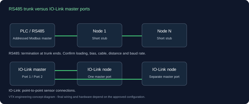
RS485 connects addressed devices along a trunk with short stubs and suitable end termination. Confirm unit loading, distance, baud rate, bias and cable before setting a node count. IO-Link connects one device to each master port.
| Feature | Units / convention | Data contract needed |
|---|---|---|
| X / Y / Z velocity | mm/s RMS, passband per channel | Address / index, signedness, integer or float, scale, byte/word order, access and refresh. |
| X / Y / Z displacement | µm peak-to-peak, frequency method | Address / index, signedness, integer or float, scale, byte/word order, access and refresh. |
| Acceleration / shock features | g, RMS / Peak / crest factor definition | Address / index, signedness, integer or float, scale, byte/word order, access and refresh. |
| Surface temperature | °C, offset and thermal response | Address / index, signedness, integer or float, scale, byte/word order, access and refresh. |
| Device status / acquisition time | Validity flags and sample age | Address / index, signedness, integer or float, scale, byte/word order, access and refresh. |
The configuration-specific register addresses and IODD are requested with the quote. A feature list alone does not define a PLC driver.
Request a map and electrical drawing →HOUSING / CONNECTION / INSTALLATION
Housing, axis orientation and cable access are physical choices. The selected Modbus register map or IO-Link IODD establishes the data interface.
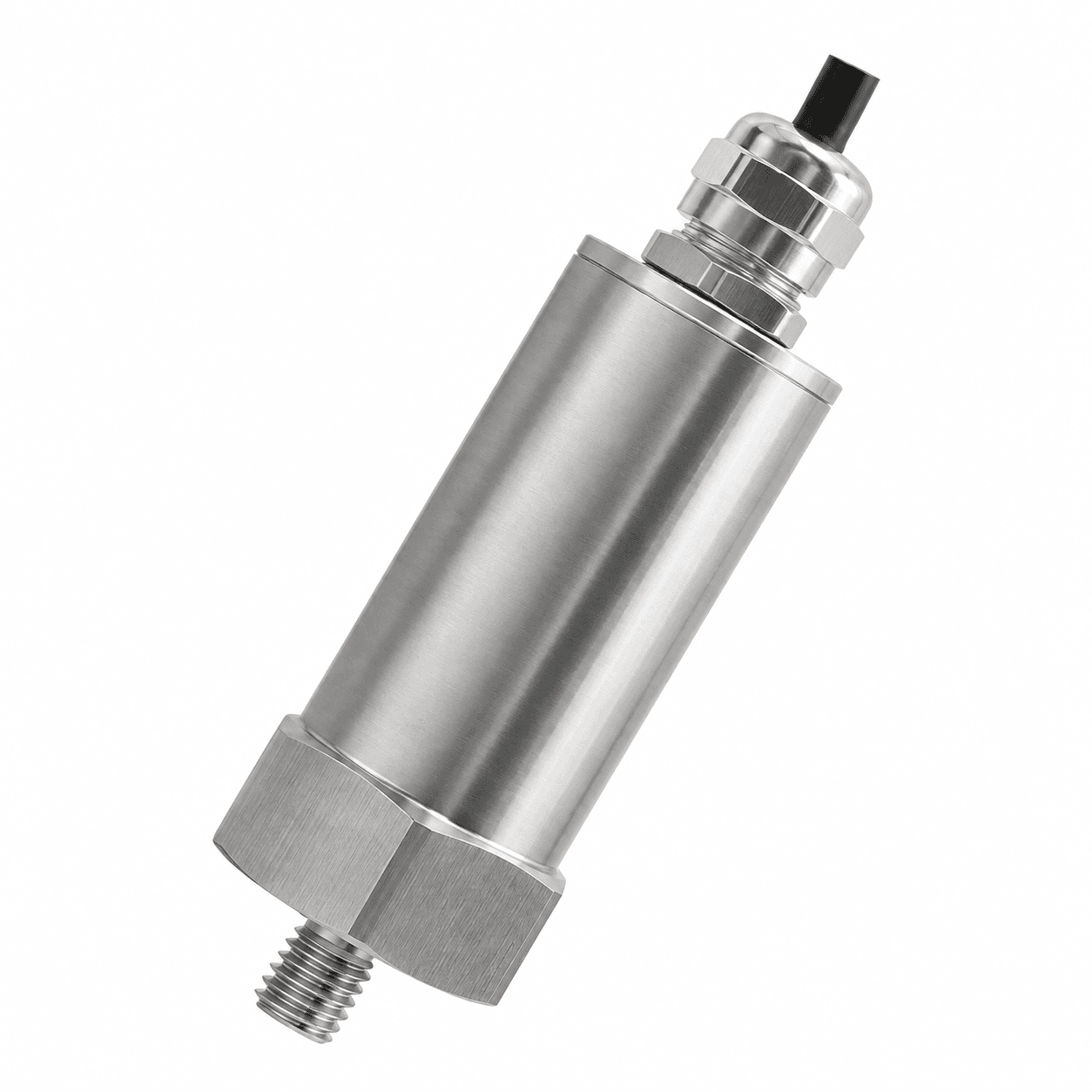
Choose a rigid bearing-housing measurement point and confirm where the temperature is sensed.
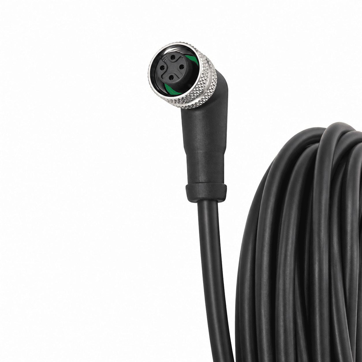
Check keying, socket count and the controlled pinout. Connector appearance alone does not identify the protocol.
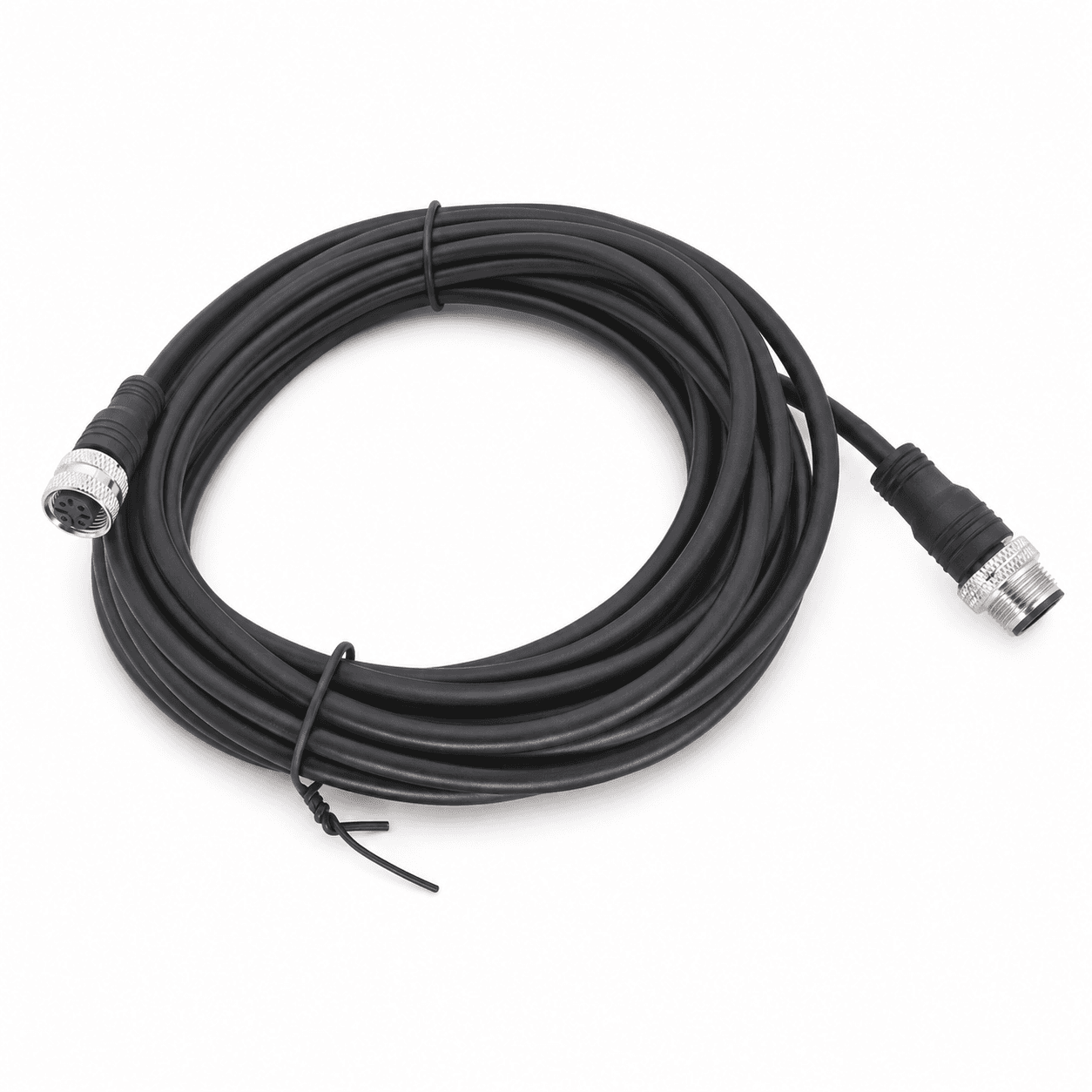
Confirm length, shielding and mating ends for the selected RS485 network or IO-Link master port.
Available guides describe the request scope. The document center lists released drawings and model-specific evidence to obtain with your quotation.
RANGE / THREAD / CONNECTOR REVIEW
| Interface | Metric request | Imperial request | Check before ordering |
|---|---|---|---|
| Velocity units | 0–10 / 20 / 25 / 25.4 / 50 mm/s RMS | 0–0.5 / 1.0 / 2.0 in/s = 12.7 / 25.4 / 50.8 mm/s | Confirm RMS, Peak or derived Peak and the original full scale |
| Mounting stud | M8 × 1.25 or M6 | 1/4–28 UNF | Pitch, thread depth, gender, seating face and torque |
| Connection | M12 4-pin | 2-pin MIL-C-5015 | Exact pinout and mating connector; not implied by connector shape |
| Other interfaces | Integral cable / protected cable | 1/2 NPT conduit entry where applicable | A conduit thread is not interchangeable with a mounting stud |
Digital features, register units and network connectors require the selected Modbus or IO-Link model documentation.
INSTALLATION KIT / FEWER LOOSE ENDS
A suitable pad, correctly wired cable and matched readout can simplify a plant rollout. Choose only the accessories your output needs in the form below.
Glue-on pads require a rigid, prepared mounting surface and qualified adhesive. Thin motor fins, fan guards and flexible covers are unsuitable default measurement points.
01 Prepared mounting pad & matched stud
02 PUR / armored cable or matched wireless gateway
03 Local display / relay monitor where applicable
04 Handheld meter for comparable spot-check readings
All kit options quoted separately. No preselected purchase obligation.IFM VVB001; Banner QM30VT2; Sick MPB10. Original axis counts and interfaces differ; do not assume a triaxial or protocol match. Review the complete original model. These are identification references only. Send the full suffix, datasheet and wiring drawing; there is no automatic drop-in or authorization claim.
List the required calibration method and traceability, enclosure rating, local conditions and certification scope. Only configuration-specific documents establish suitability; a housing style or series name is not evidence.
Share an asset list, measurement points per asset, control architecture, cable lengths and destination. Request a pilot configuration before a larger rollout. Pricing and lead time follow the reviewed bill of materials.
| Request code | Item | Quantity basis | Fit and environment review |
|---|---|---|---|
| VTX-ACC-PAD | Prepared glue-on pad / fin-mount adapter review | per mounting point | Rigid load path, actual fin geometry, adhesive, cure, temperature and installed response. |
| VTX-ACC-CBL | 5 m PUR / armored cable request | per cable assembly | Length, sheath, connector coding, pinout, cable restraint and temperature. |
| VTX-DIN | Local display and relay monitor | per monitored channel | Loop powering, engineering units, relay ratings and reset. |
| VTX-PEN | Portable vibration spot-check meter | per instrument | Detector, bandwidth, contact probe / mount and calibration scope. |
For a pilot, workshop or OEM rollout, request line-item unit prices at the exact quantity and destination. Include studs, cable lengths, calibration, freight and warranty terms in the quote.
Download quotation comparison CSV ↓PLANT-WIDE QUOTE / CAD REVIEW
Include the machine, original model and control input. Attach a nameplate or asset list and request the drawings and records needed for purchasing.
[email protected]Prefilled email carries your current selections. Add the listed files in your email client.
Ask for sensor-only and installation-kit line items at your exact quantity. Studs, calibration scope, warranty and delivery will appear in the written quote.
Download the asset-list CSVVibration Transmitters | Plant-wide vibration monitoring RFQ Name: Request profile: Configuration review Request purpose: Configuration advice / project review Band: Confirm band and response tolerance Exact quantity: To confirm Wireless kit: Not selected Documents requested: None Company / plant: Reply email: Series entry: VTX-MOD Machine: Electric motors, pumps & fans Output: RS485 Modbus [triaxial vibration + temperature] Range: Confirm range / digital features in brief Connector / mounting: Other / confirm with drawing Mounting thread: Confirm thread, gender and depth in brief Connection exit: Confirm from model / clearance drawing Original pinout to review: To confirm from drawing Detector: Confirm per configuration Original model: Not specified Quantity band: 1-5 Accessories: None Source: /rs485-modbus-io-link-vibration-sensors/ Operating speed / RPM: To confirm Ambient / bearing temperature: To confirm PLC / receiving system: To confirm Destination country / site: To confirm Interface and operating requirements: To confirm during configuration review Project brief: Configuration, certification, compatibility, price and delivery subject to written review.
OTHER SIGNAL PATHS