4–20mA transmitter
Provides an integrated process value such as velocity RMS to a compatible analog input. Useful for continuous overall trends and alarm logic, with configured bandwidth and response.
 Vibration Transmitters
ENGINEERING GUIDE / REVIEWED 10 NOV 2026
Separate the measurement scale from the machine alarm. Match the machine evaluation method, then verify the signal path into the PLC.
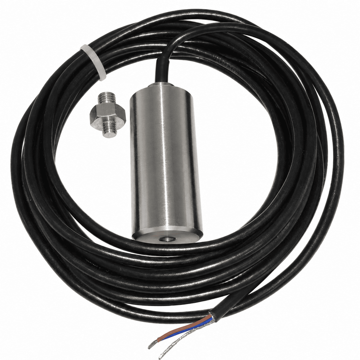
SEVERITY / MACHINE-SPECIFIC EVALUATION
ISO 20816 evaluates vibration for specified machine groups and operating conditions. Overall magnitude and changes from a baseline both matter.
Qualitative orientation only, not a reproduced ISO chart or numerical acceptance criterion. Use the applicable standard edition and machine-specific boundaries.
| Decision | Required information |
|---|---|
| Machine & standard part | Machine type, coupling, power, operating speed, support stiffness and applicable ISO part |
| Measurement basis | Housing / shaft location, direction, steady-state condition, RMS / Peak and frequency band |
| Action policy | Baseline trend, OEM limits, run-up behavior, consequence of failure and machine protection design |
| Special machines | Intentional screen motion, reciprocating machines and slow-speed assets need their own review |
The official ISO 20816-3:2026 scope was published in October 2026 and supersedes the 2022 edition. Confirm the part and edition your project adopts. The standard addresses overall vibration evaluation; it does not by itself diagnose rolling-bearing defects.
ISO 10816 remains common in existing asset records. Do not treat that label as a sensor certification or copy its thresholds into every PLC.
PASSIVE AI / TWO-WIRE LOOP
Active AI modules can supply loop power themselves. Follow the module drawing rather than adding a second supply.
Rload,max = (Vsupply,min − VTX,min − Vother) / Idesign − Rcable − Rbarrier
Use the actual maximum operating / fault current and minimum supply. Do not double-count resistive and fixed drops. Check actual supply tolerance. Grounding and shielding follow the installation EMC plan.
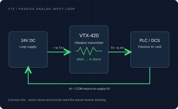
Example range: 0–25 mm/s RMS. Colors illustrate configurable status; they are not ISO alarm / trip limits.
PLC ENGINEERING-UNIT CHECK
v = (I − 4) ÷ 16 × full-scale range
Scaling only. Out-of-range / fault currents require model-specific handling; this tool sets no alarm or trip threshold.
For 0–25.4 mm/s RMS, 12mA is 12.7 mm/s. For 0–25 mm/s RMS, 12mA is 12.5 mm/s. Neither midpoint is an automatic ISO warning threshold.
ACCELEROMETER VS VIBRATION SENSOR
Provides an integrated process value such as velocity RMS to a compatible analog input. Useful for continuous overall trends and alarm logic, with configured bandwidth and response.
Provides a waveform needing suitable excitation and acquisition. It supports spectral and transient analysis; a normal 4–20mA AI is not a waveform acquisition channel.
Can report multiple features, temperature or selected spectra if supported. Confirm the actual protocol, sampling, bandwidth and latency; not every node streams raw waveforms.
Velocity, acceleration and displacement are different quantities. Sine-wave conversions require the frequency and amplitude convention; complex machine motion has no universal single conversion factor.
For a concrete original-model wiring reference, see the Hansford HS-420 datasheet. Its ratings and pinout belong to that original product, not a VTX specification.
Use raw counts corresponding to the configured module’s 4mA and 20mA endpoints. Check input validity and fault flags before applying engineering scaling.
// RawMin and RawMax come from this AI channel setup.
Normalized := NORM_X(MIN := RawMin, VALUE := RawValue,
                     MAX := RawMax);
Velocity := SCALE_X(MIN := 0.0, VALUE := Normalized,
                    MAX := FullScaleMmS);
// Evaluate diagnostics before using Velocity for alarms.
One configured 4–20mA example uses RawMin=0 and RawMax=27648. A 0–20mA channel needs different 4mA endpoints.
Siemens conversion documentation ↗// Use the actual input representation for this module.
Velocity := (RawValue - RawAt4mA)
/ (RawAt20mA - RawAt4mA) * FullScaleMmS;
// If the module already provides engineering units,
// configure Low/High Signal and Engineering directly.Some ControlLogix modules provide scaled floating-point data. Confirm the module, channel format and signal span before using integer counts.
Rockwell channel configuration ↗Current and voltage inputs use different hardware configurations. Follow the module wiring document. Fault thresholds such as undercurrent are enabled only when supported by the selected transmitter and input module.
Enter the actual counts at 4mA and 20mA for the configured module. The initial values illustrate one Siemens 4–20mA configuration.
Use minimum supply and the model’s maximum operating / fault current. Enter resistive drops and fixed drops once.
This budget covers voltage only. Intrinsic-safety entity parameters, isolation, tolerances, temperature and the full loop must be checked separately.
Enter the limits approved for your machine and applicable standard part. Initial values are an example worksheet. Assign the machine’s alarm/trip policy separately.
| mm/s RMS | in/s RMS | Loop current |
|---|---|---|
| 1.40 | 0.055 | 4.88 mA |
| 2.80 | 0.110 | 5.76 mA |
| 4.50 | 0.177 | 6.83 mA |
MATING CONNECTOR / MOUNT / CABLE
Confirm the drawing for both ends of the connection. A familiar plug or thread does not establish wiring or mechanical compatibility.
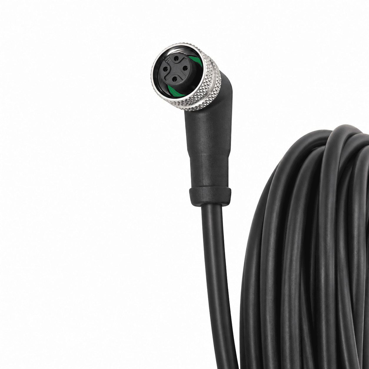
Confirm coding, pin assignment and cable-exit clearance.
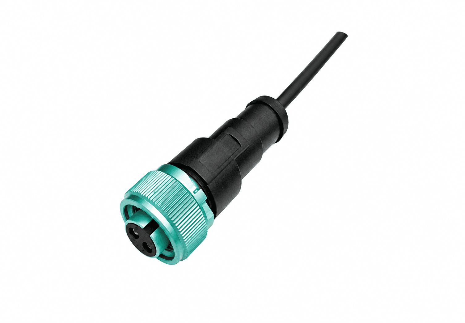
Check mating gender, contact assignment and locking clearance.
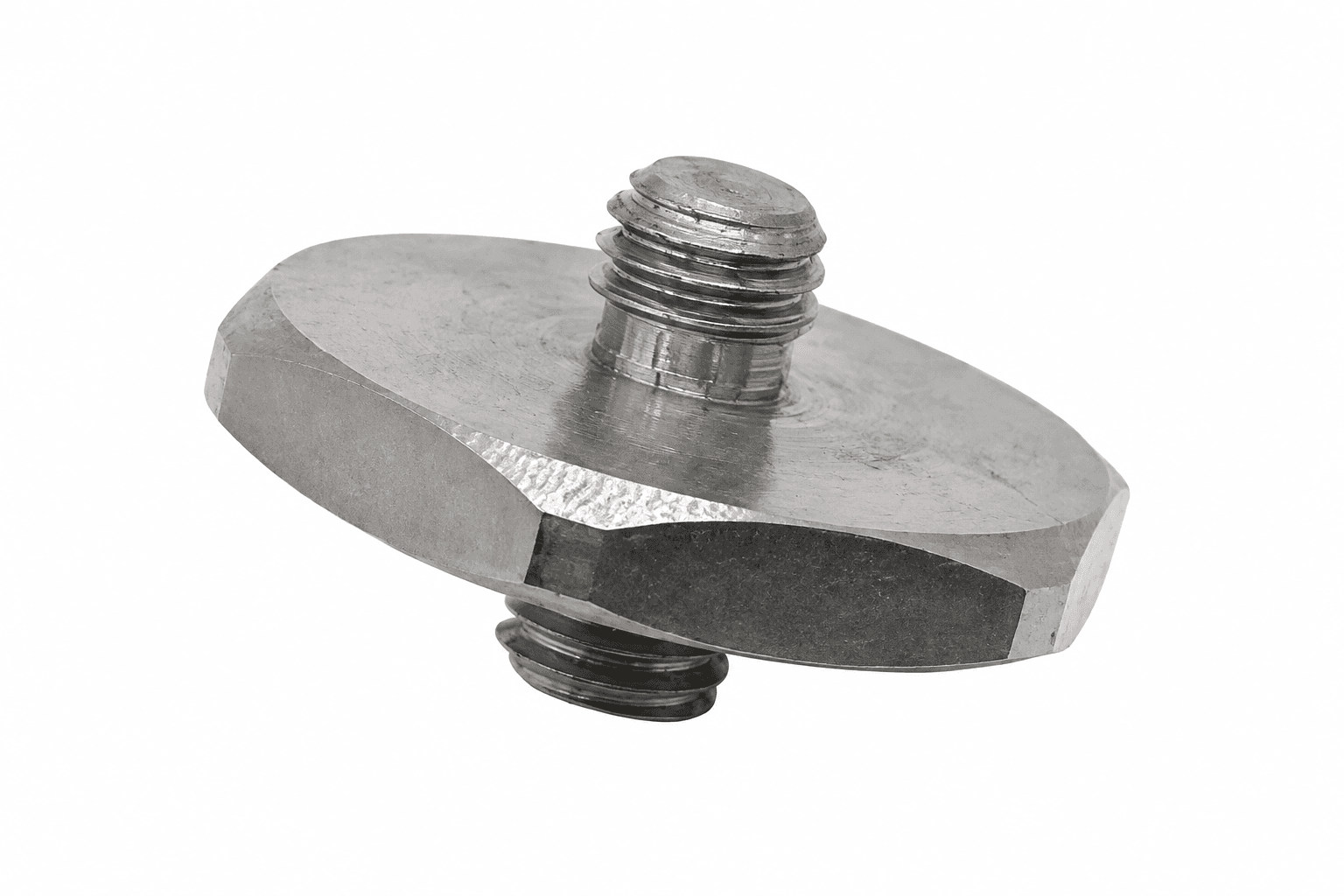
Match pitch, gender, usable depth and seating faces.
PLANT-WIDE QUOTE / CAD REVIEW
Include the machine, original model and control input. Attach a nameplate or asset list and request the drawings and records needed for purchasing.
[email protected]Prefilled email carries your current selections. Add the listed files in your email client.
Ask for sensor-only and installation-kit line items at your exact quantity. Studs, calibration scope, warranty and delivery will appear in the written quote.
Download the asset-list CSVVibration Transmitters | Plant-wide vibration monitoring RFQ Name: Request profile: Configuration review Request purpose: Configuration advice / project review Band: Confirm band and response tolerance Exact quantity: To confirm Wireless kit: Not selected Documents requested: None Company / plant: Reply email: Series entry: Unspecified Machine: Electric motors, pumps & fans Output: 2-wire 4–20mA velocity [RMS / Peak by configuration] Range: Confirm range / digital features in brief Connector / mounting: Other / confirm with drawing Mounting thread: Confirm thread, gender and depth in brief Connection exit: Confirm from model / clearance drawing Original pinout to review: To confirm from drawing Detector: Confirm per configuration Original model: Not specified Quantity band: 1-5 Accessories: None Source: /iso-20816-vibration-severity-chart-4-20ma-wiring/ Operating speed / RPM: To confirm Ambient / bearing temperature: To confirm PLC / receiving system: To confirm Destination country / site: To confirm Interface and operating requirements: To confirm during configuration review Project brief: Configuration, certification, compatibility, price and delivery subject to written review.